Spar Capstrip Layout
While reading some of the Bearhawk group posts, and talking with a couple of other builders, I noticed there seems to be a lot of confusion about how the spar and capstrips are layed out. It was very confusing for me as well, and took considerable time studying the plans before it finally dawned on me how it all fits. Seems simple now. I'm just starting to drill the second main spar and thought I would take some pictures and hope this will make it a little easier to understand.
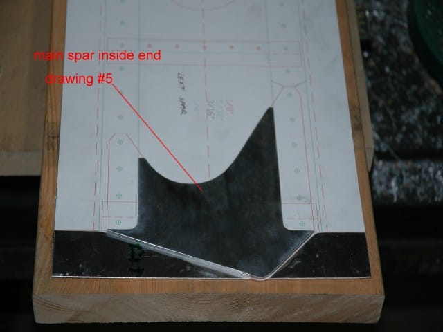
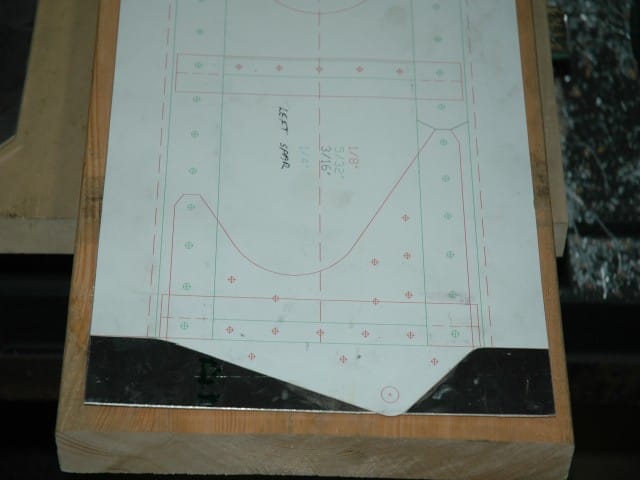
I started by making a full size drawing of the spar web and related pieces in AutoCadd, and placed it on top of the spar blank. This is the front view of the spar. I'm not going to bend the flanges (depicted by the dashed red line) until after I drill everything. The inside main spar end goes next to the spar blank
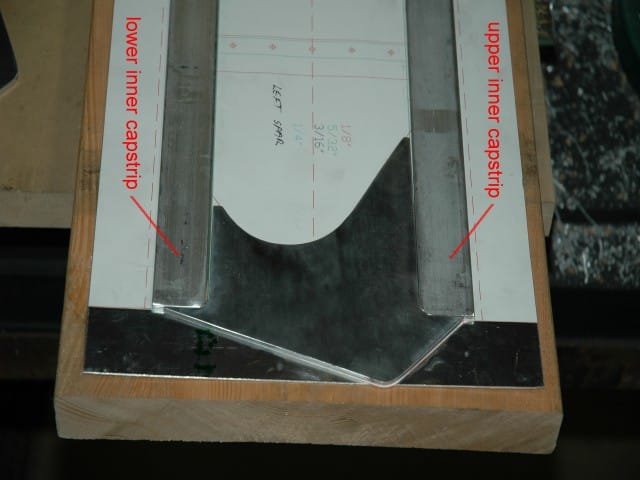
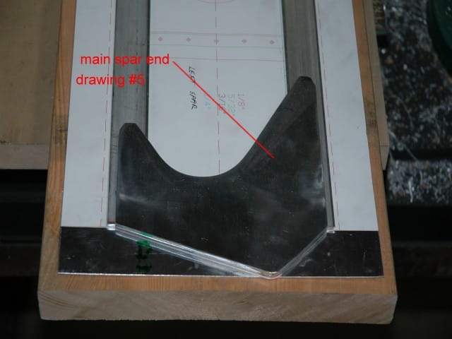
The 142-1/8" long inner capstrips go on top and bottom of the inside end. The main spar end goes outside of the inside end and the inner capstrips.
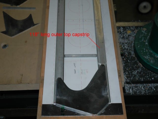
A 1/8" thick spacer goes between the inner capstrips. What I've shown so far is the same for both sides of the spar, front and rear. So you have spar blank, inner main spar end, two long capstrips, main spar end, and a short spacer at rib location #2. On the front side of the spar only, there is a 118" long capstrip butted up against the main spar end and on top of the upper inner capstrip. This was the engineering change made after the wing load tests. The lower inner capstrip does not get doubled up until 30-3/8" from the root end. The rear side of the spar does not have doubled up capstrips until 41-3/4" from the root end.
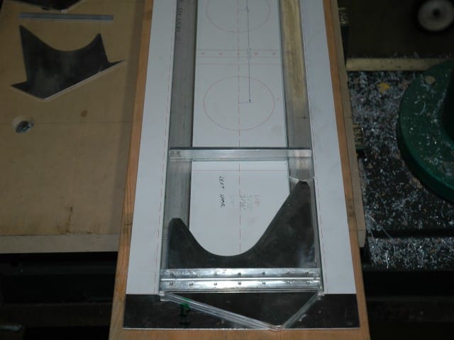
A longer spacer is placed on top of the first short spacer and butts up against the 118" long upper outer capstrip. You only have to use this longer spacer on the front of the spar in the locations that have the doubled up top capstrip and don't have a doubled up lower capstrip. As you can see, by putting the longer spacer on, the rib attach angles will have something nice and flat to attach to.